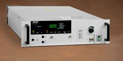
Amplifier, TWT , Ku-Band, 400W
Amplifier, TWT , Ku-Band, 400W
SPECIFICATIONS, VZU-6994
Electrical
Frequency 13.75 to 14.50 GHz, 12.75 to 14.50 GHz,
14.7 to 15.2 GHz, or 13.75 to 14.80 GHz
Output Power
TWT 400 W min. (56.02 dBm), 13.75 to 14.50 GHz,
and 13.75 to 14.80 GHz;
350 W min. (55.44 dBm), all others
Flange 350 W min. (55.44 dBm), 13.75 to 14.50 GHz
and 13.75 to 14.80 GHz;
275 W min. (54.39 dBm), all others
Bandwidth 500 to 1750 MHz, depending on confi guration
Gain 73 dB min. at rated power output;
78 dB min. at small signal
RF Level Adjust Range 0 to 20 dB
Gain Stability ±0.25 dB/24hr max.
(at constant drive and temp.)
Small Signal Gain Slope ±0.015 dB/MHz max., 400 W confi gurations
±0.02 dB/MHz max., 350 W confi gurations
Small Signal Gain Variation 1.0 dB pk-pk across any 80 MHz band;
3.0 dB pk-pk across the entire passband,
13.75 - 14.80 confi guration;
2.5 dB pk-pk across the entire passband
all others;
4.5 dB pk-pk across passband, with linearizer
Input VSWR 1.3:1 max.
Output VSWR 1.3:1 max.
Load VSWR 2.0:1 max. operational; any value for operation
without damage
Phase Noise
IESS Phase Noise Profi le -12 dBc
AC Fundamental -42 dBc
Sum of All Spurs -50 dBc
AM/PM Conversion 2.5°/dB max. for a single carrier at
6 dB below rated power (at 4 dB below
rated power with optional linearizer)
Harmonic Output -60 dBc at rated power, second and third
harmonics
Noise Density <-150 dBW/4 kHz in Receive/Reject Band
<-65 dBW/4 kHz in Passband to 18 GHz
<-60 dBW/4 kHz in Passband w/linearizer
Electrical (continued)
Intermodulation -24 dBc max. with two equal
carriers at total output power 7
dB (4 dB with optional integral
linearizer) below rated singlecarrier
output; -22 dBc max. at
7 dB OBO (4 dB w/lin.) for 14.7
- 15.2 GHz confi g.
Group Delay 0.01 ns/MHz linear max.
(in any 80 MHz band) 0.001 ns/MHz2 parabolic max.
0.5 ns pk-pk ripple max.
Environmental (Operating)
Primary Power 110 - 240 VAC ±10%,
single phase 47-63 Hz
(100 VAC optional)
Power Consumption 1.3 kVA typ., 1.4 kVA, max. for
350W confi gurations;
1.35 kVA typ., 1.5 kVA max. for
400W confi guration
Power Factor 0.95 min.
Ambient Temperature -10° to +50°C operating
-40° to +70°C non-operating
Relative Humidity 95% non-condensing
Altitude 10,000 ft. with standard adiabatic
derating of 2°C/1000 ft., operating;
40,000 ft., non-operating
Shock and Vibration Designed for normal transportation
environment per Section 514.4
MIL-STD-810E. Designed to
withstand 20G at 11 ms (1/2
sine pulse) in non-operating
confi guration.
Acoustic Noise 65 dBA @ 3 ft. from amplifi er
Mechanical
Cooling (TWT) Forced air with integral blower
Rear air intake & exhaust
RF Input Connection Type N female
RF Output Connection WR 75 waveguide fl ange,
grooved with UNC 2B 6-32
threaded holes
RF Output Monitor Type N female
Dimensions (W x H x D) 19 x 5.25 x 24 in.
(483 x 133 x 610 mm)
Weight 60 lbs (27.3 kg) max.